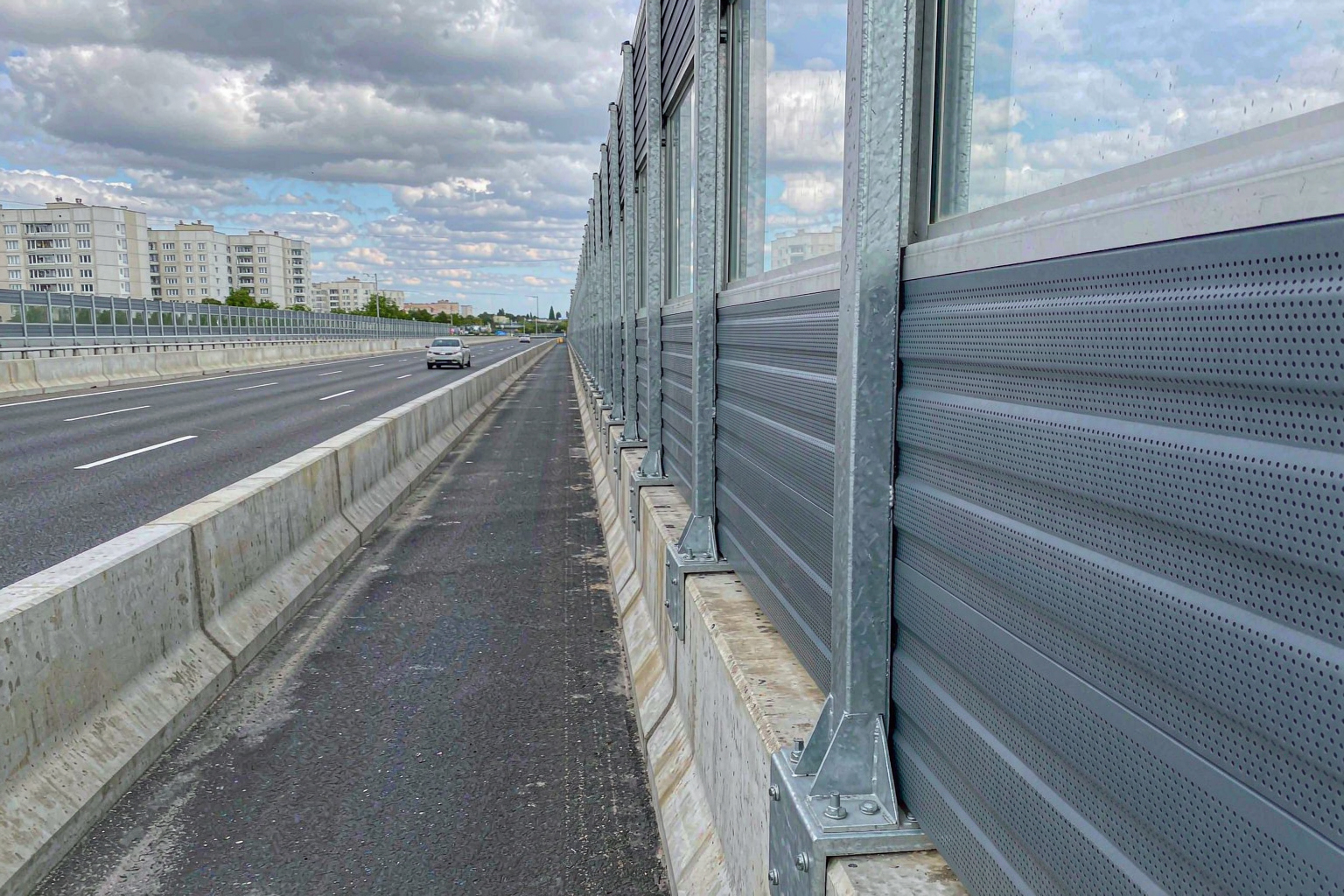
Conclusion first. Elevated viaducts and river crossings generate the loudest, farthest-traveling complaints in any city — the deck sits 5 to 15 meters above ground, tire noise shoots straight into the bedrooms of high-rise residents along the corridor, and ground-level barriers cannot help. The bridge sound barrier is purpose-built for exactly this section: hot-dip galvanized steel posts rooted directly in the crash barrier by bolted anchoring, upper transparent PC panels (light transmission ≥88%, so drivers keep full sightlines) over lower perforated absorptive panels filled with 80 mm centrifugal glass wool (48 kg/m³, NRC ≥ 0.85), a weighted sound reduction of Rw ≥ 30 dB, and field-measured 10–20 dB(A) at receivers beside the deck. One rule we learned the hard way: on bridges, the structural engineering demands more attention than the acoustics — posts need a bridge-specific load calculation, panels need wind-vibration fatigue checks, and anchors must dodge expansion joints and drainage lines. Send the bridge drawings and the exceeding points; the noise prediction and layout plan come back the same day.
Rooting on the bridge: three gates — load, wind vibration, expansion joints. A ground barrier stands on its own foundation; a bridge barrier can only stand on the crash barrier, which was designed for vehicle impact, not for a crown of steel and panels. So the workflow starts with the bridge drawings from the owner or design institute: confirm the barrier type (concrete, steel or combined) and any precast inserts — concrete parapets take bolted connections on the inserts, bare concrete gets chemical anchors verified by pull-out tests, and steel parapets need their stiffeners and weld margins checked. Second gate, wind vibration: decks sit one to two wind zones above ground and passing traffic adds pulsating pressure, so every post-to-panel connection is fatigue-checked, with extra margin in typhoon-prone coastal corridors. Third gate, the deck's own furniture: post positions dodge expansion joints, transverse drainage pipes and street-light foundations within the 2.0–2.5 m spacing window. All three gates pass before any acoustic tuning matters — anything else is a hidden liability.
How the two panel layers divide the work. The split section is not styling — each layer has a job. The lower absorptive band (1–1.5 m high) sits closest to the source: tire-to-deck noise is born there, and the perforated facing over 80 mm glass wool absorbs it on the spot, suppressing the crawl of sound up the deck. The upper transparent band blocks what remains while preserving two sightlines — the driver's view of the road and the residents' view of the city; 5–10 mm PC solid sheet transmits ≥88% of light and still reaches Rw 28–31 dB. Where receivers are high-rise, the transparent band is extended upward to widen the acoustic shadow; where low-rise housing dominates, overall height drops and the budget shifts into thicker absorption. Many contracts also fold in the anti-throw function: the gap between panel base and parapet is sealed, and the panel assembly is impact-checked to anti-throw-net criteria — one structure, two duties, and a construction step saved over fitting a separate net.
Field lessons. Posts versus drain pipes: on an urban expressway the deepening drawings laid posts at a uniform 2.5 m, and site marking found three of them landing squarely on transverse drainage pipes — bridge-attachment drawings and reality disagree regularly. Our fix was to move site marking ahead of deepening: post positions are verified span by span on site, dodging joints, drains and light-pole bases before shop drawings are issued. Wind-vibration loosening: on a coastal river bridge fitted with ordinary bolts, a two-year inspection found loosened connections and rattling panels — deck wind plus traffic pulsation fatigues connections far faster than ground conditions ever do. The retrofit re-verified the fatigue class across the line, switched to self-locking bolts with lock washers, and folded barrier inspection into the bridge's periodic checks. PC yellowing: an early cost-saving project used plain PC sheet, which hazed within three years and drew complaints of a "frosted glass wall". Double-sided UV co-extruded sheet is our standard, with light-transmission retention written into the material schedule — the price difference is small and the difference in year three is not.
Color and streetscape: the bill city bridges cannot skip. A barrier runs for kilometers through a built-up district, and owners and planning departments often care as much about how it looks as how it performs. The leverage is all in the proposal stage: powder-coated posts and absorptive panels take any RAL color (light grays and blue-grays along riverfront landscapes, dark gray on trunk roads, wood-grain transfer on scenic projects); top profiles come straight, arced or inclined — arcs attenuate diffraction slightly better, straights cost least, and inclined tops lean toward high-rise receivers to stretch the shadow; even the ratio of transparent to absorptive band and the exposed post width are tunable, since the more transparent the run, the lighter it reads. Landscape requirements belong in the deepening drawings, with color samples approved on the bridge before batch coating — far cheaper than repainting after installation. One line we hold: streetscape never overrides load or ventilation; every restyle goes back through the calculation.
Verification and supply. Four checks before signing: demand the bridge-specific load calculation (barrier type, anchoring method, overturning result — a design institute stamp is even better); specify double-sided UV co-extruded PC in the material schedule; require site marking before deepening, with the dodging of joints and services drawn into shop drawings; and match connection hardware to the fatigue class — ask about bolt grade and anti-loose provisions, because bridge wind makes ground-grade hardware fail in two years. Production runs 15–25 days: posts hot-dip galvanized, panels composite on the line, PC sheets UV-co-extruded and cut, modules numbered for the site. Installation works nights without closing the deck below — anchoring with pull-out tests, panel lifting, sealing and finishing — and acceptance closes with receiver-point insertion loss measured, anchor pull-out re-verified, and the full report handed over with the barrier.